

Product Descriptions
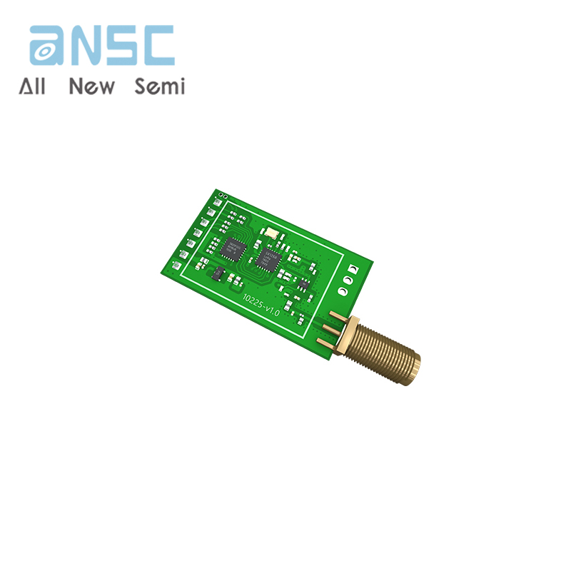
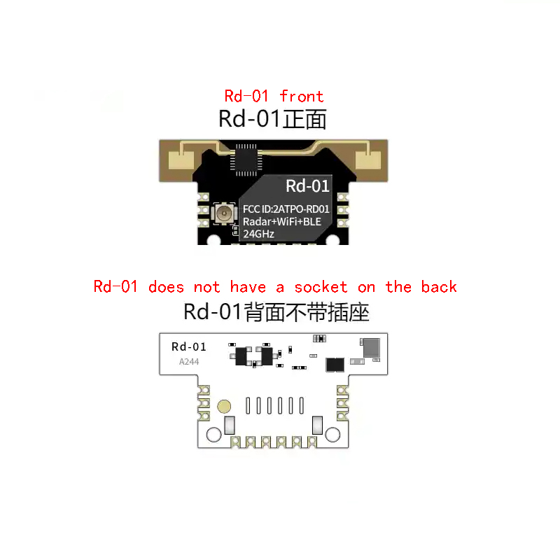
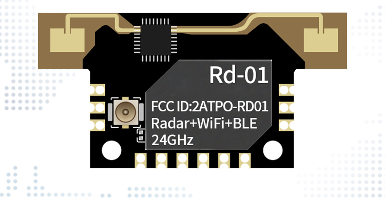
Rd-01 is a radar module that supports Wi Fi&BLE. The radar is equipped with the S3KM111L chip and operates in the 24GHzk band, with a modulation bandwidth of up to 1GHz per frequency. The working principle is to use FMCW frequency modulation continuous wave to detect human targets in a set space, combined with radar signal processing and precise human sensing algorithms, to achieve high-sensitivity human presence state sensing, identify human bodies in motion and stationary states, and calculate auxiliary information such as target distance.
The Wi Fi&BLE section is equipped with BL602 chip as the core processor, supporting Wi Fi 802.11b/g/n and BLE5.0 protocols. This product is mainly used in indoor scenes to detect whether there is movement or micro motion of the human body in the sensing area. It transmits the detection results in real-time through Wi Fi&BLE and provides a visual configuration tool that can easily configure the sensing distance range, sensing sensitivity in different intervals, and unmanned delay time. Supports GPIO and UART output, as well as Wi Fi&BLE wireless configuration of radar parameters, which can be flexibly applied to different intelligent scenarios and terminal products.
Product Specifications
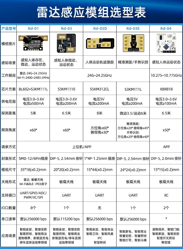
| 模组型号 Module model | Rd-01 |
| 模组封装 Module packaging | SMD-12,兼容贴片/排针/插座等多种装配方式 SMD-12, Compatible with various assembly methods such as patch, pin, socket, etc |
| 尺寸(mm) Size(mm) | 35.0*18.0*3.6(±0.2)MM |
| 天线形式 Antenna form | 雷达:板载天线 Radar: onboard antenna |
| Wi-Fi&BLE:IPEX mount | |
| 频谱范围 Spectrum range | Radar:24G~24.25GHz |
| Wi-Fi:2400~2483.5MHz | |
| 工作环境 Work environment | -40℃~85 ℃ |
| 存储环境 Storage environment | -40℃~125°C,<90%RH |
| 供电范围 Power supply range | 供电电压3.0V~3.6V,供电电流≥500mA Supply voltage 3.0V~3.6V,supply current≥500mA |
| 支持接口 Support interfaces | UART/GPIO/ADC/PWM/IIC/SPI |
| IO口数量 Number of IO ports | 8个 Default 8 |
| 串口速率 Series Rate | 默认256000bps Default 256000bps |
| 安全性 Safety | WPS/WEP/WPA/WPA2 Personal/WAP2 Enterprise/WPA3 |
| Flash | 默认2MByte Default 2MByte |
| 脚序 Foot sequence | 名称 Name | 功能说明 Function Description |
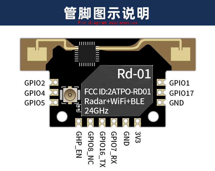
| 1,11 | GND | 接地 |
| 2 | GPIO17 | GPIO17/SPI_MOSI/MISO/IIC_SDA/PWM-CH2/JTAG_TCK/TMS |
| 3 | GPIO1 | GPIO1/SPI_MOSI/MISO/IIC_SDA/PWM_CH1 |
| 4 | GPIO2 | GPIO2/SPI_SS/IIC_SCL/PWM_CH2 |
| 5 | GPIO4 | GPIO4/SPI_MOSI/MISO/IIC_SCL/PWM_CH4/ADC_CH1 |
| 6 | GPIO5 | GPIO5/SPI_MOSI/MISO/IIC_SDA/PWM_CH0/ADC_CH4/JTAG_TMS/TCK |
| 7 | CHIP_EN | 默认作为芯片使能,高电平有效。 |
| 8 | GPIO8 | Bootstrap/GPIO8/SPI_MOSI/MISO/IIC_SCL/PWM_CH3 |
| 9 | GPIO16 | TXD/GPIO16/SPI_MOSI/MISO/IIC_SCL/PWM_CH1/JTAG_TMS/TCK |
| 10 | GPIO7 | RXD/GPIO7/SPI_SCLK/IIC_SDA/PWM_CH2/JTAG_TDO/TDJ |
| 12 | 3V3 | 3.3V供电;外部供电电源输出电流建议在 500mA 以上 |
| Note: As a Bootstrap, when GPO8 is powered on and reaches a high level, the module enters burning mode; When the power on moment is low, the module starts normally. | ||
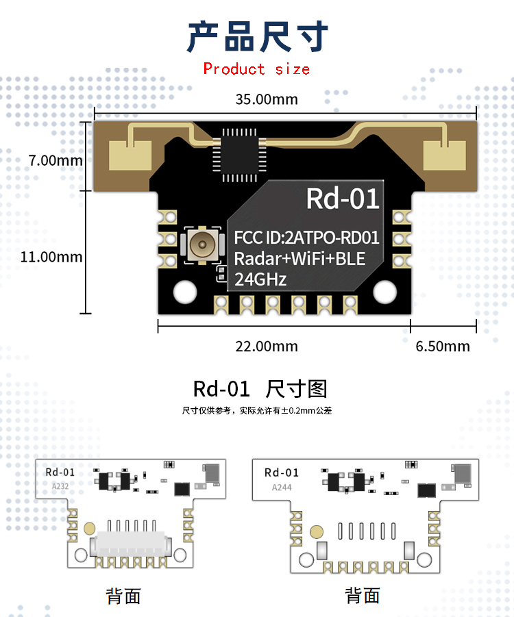
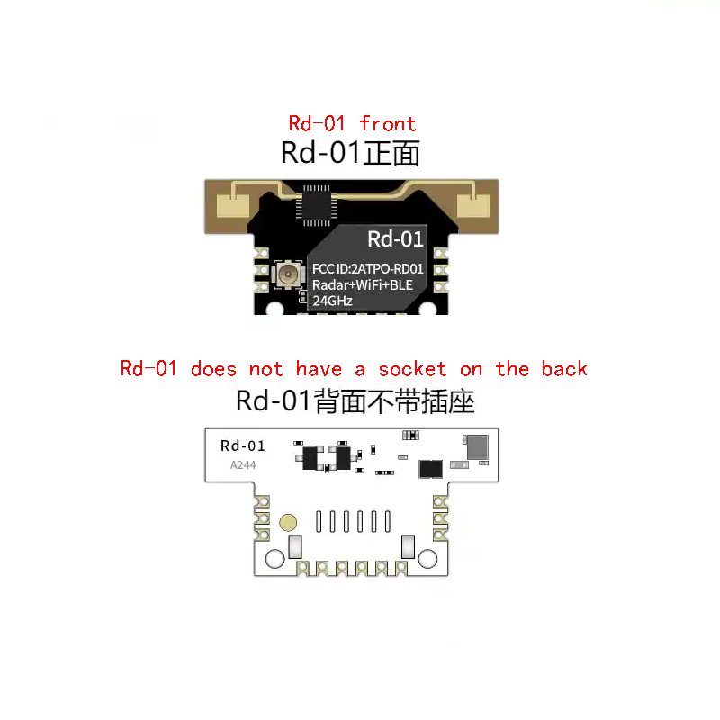
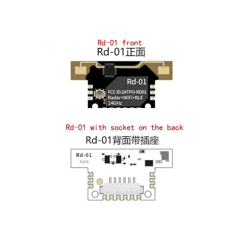
Note: The Rd-01 module comes in both socket and non socket forms.
Modules with sockets can be connected to the motherboard using ribbon cables, and the installation position is flexible. The socket uses standard 1 * 6P-1.25mm spacing interfaces, and the positioning holes on the module can be used for screw fixation.
Modules without sockets can be SMT mounted onto the motherboard to improve assembly efficiency.
Product instructions
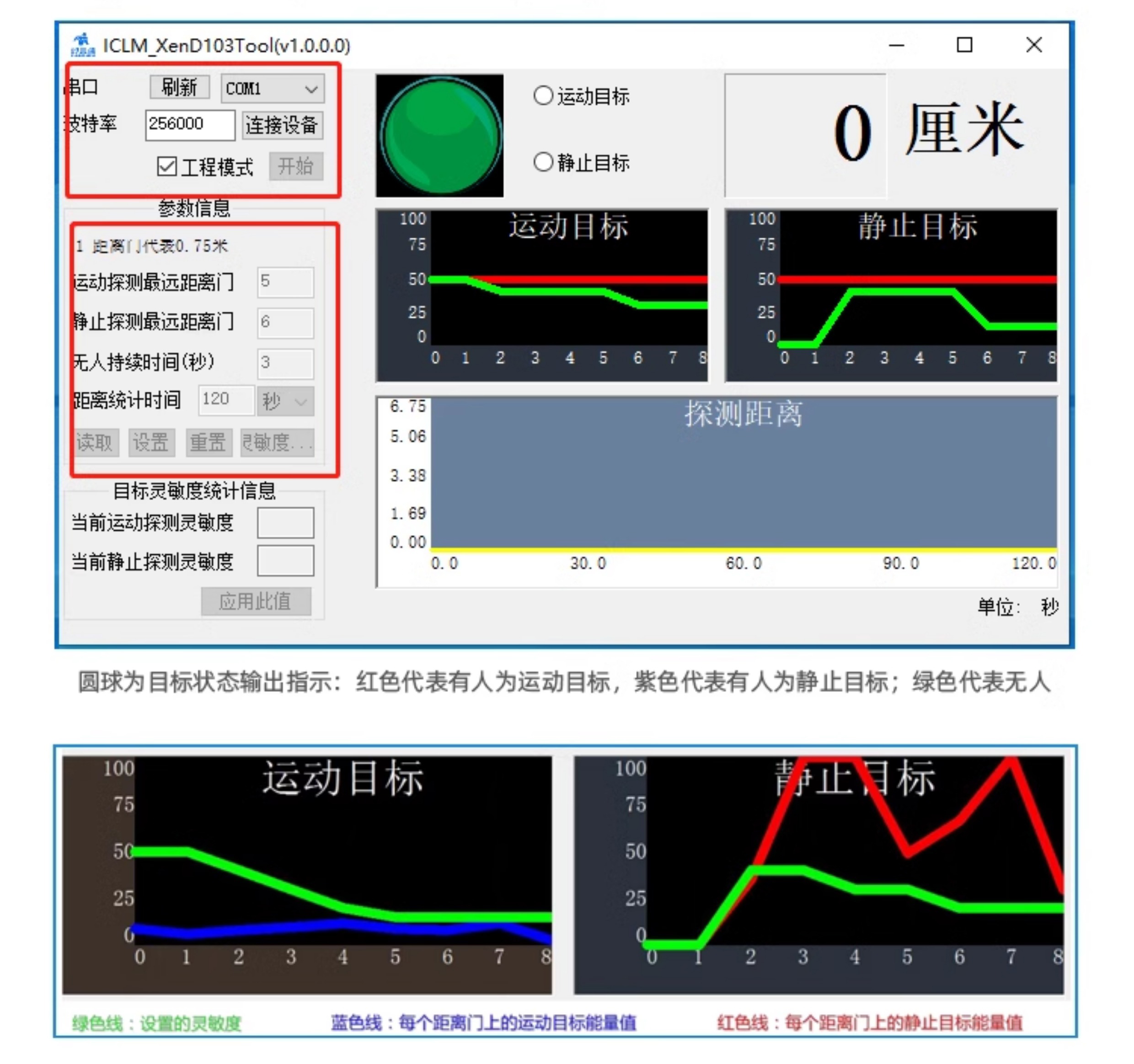
Instructions for using upper computer tools:
1. Connect the module serial port correctly using a USB to serial tool;
2. Select the corresponding serial port number in the upper computer tool, set the baud rate to 256000, select the engineering mode, and click to connect the device;
3. After successful connection, click the start button, and the detection results and data will be displayed on the graphical interface on the right side;
4. After connecting, if the start button is not clicked, or if the stop button is clicked after starting, the mode parameter information can be read or set;
Note: Parameters cannot be read or configured after clicking start. Configuration can only be performed after stopping.
The interface and common functions of the upper computer tool are shown in the following figure:
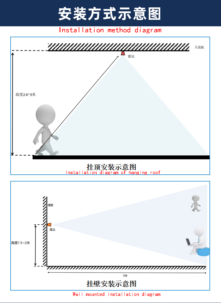
The recommended installation positions on the motherboard are as follows:
1. Try to ensure that the radar antenna is directly facing the area to be detected, and that the surrounding area of the antenna is open and unobstructed.
2. To ensure that the installation position of the radar is firm and stable, the shaking of the radar itself will affect the detection effect.
3. Ensure that there is no object movement or vibration on the back of the radar. Due to the penetrability of radar waves, the antenna signal back lobe may detect moving objects behind the radar. Metal shielding covers or metal backplates can be used to shield the radar back lobe and reduce the impact of objects on the radar back.
4. The theoretical distance accuracy of radar is the result obtained through special algorithm processing based on a physical resolution of 0.75 meters. Due to differences in target size, status, RCS, etc., the distance accuracy of the target may fluctuate; At the same time, the distance may also fluctuate slightly.
5. In order to meet the performance of the onboard antenna, it is prohibited to place metal parts around the antenna and keep them away from high-frequency devices.
This product needs to be installed in a suitable environment, and the following environments will affect the detection effect:
1. There are non-human objects that are constantly moving within the sensing area, such as animals, curtains that are constantly swinging, and large green plants facing the air outlet.
2. There are large areas of strong reflectors in the sensing area, which can cause interference when facing the radar antenna.
3. When installing on a wall, external interference factors such as air conditioning and electric fans at the top of the room need to be considered.
Product Show
Payment&Transportation

Official Certificate&Certificate

Multiple product supply

Company office environment

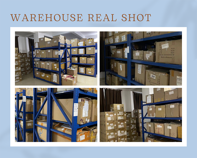
Warehouse Real Shot
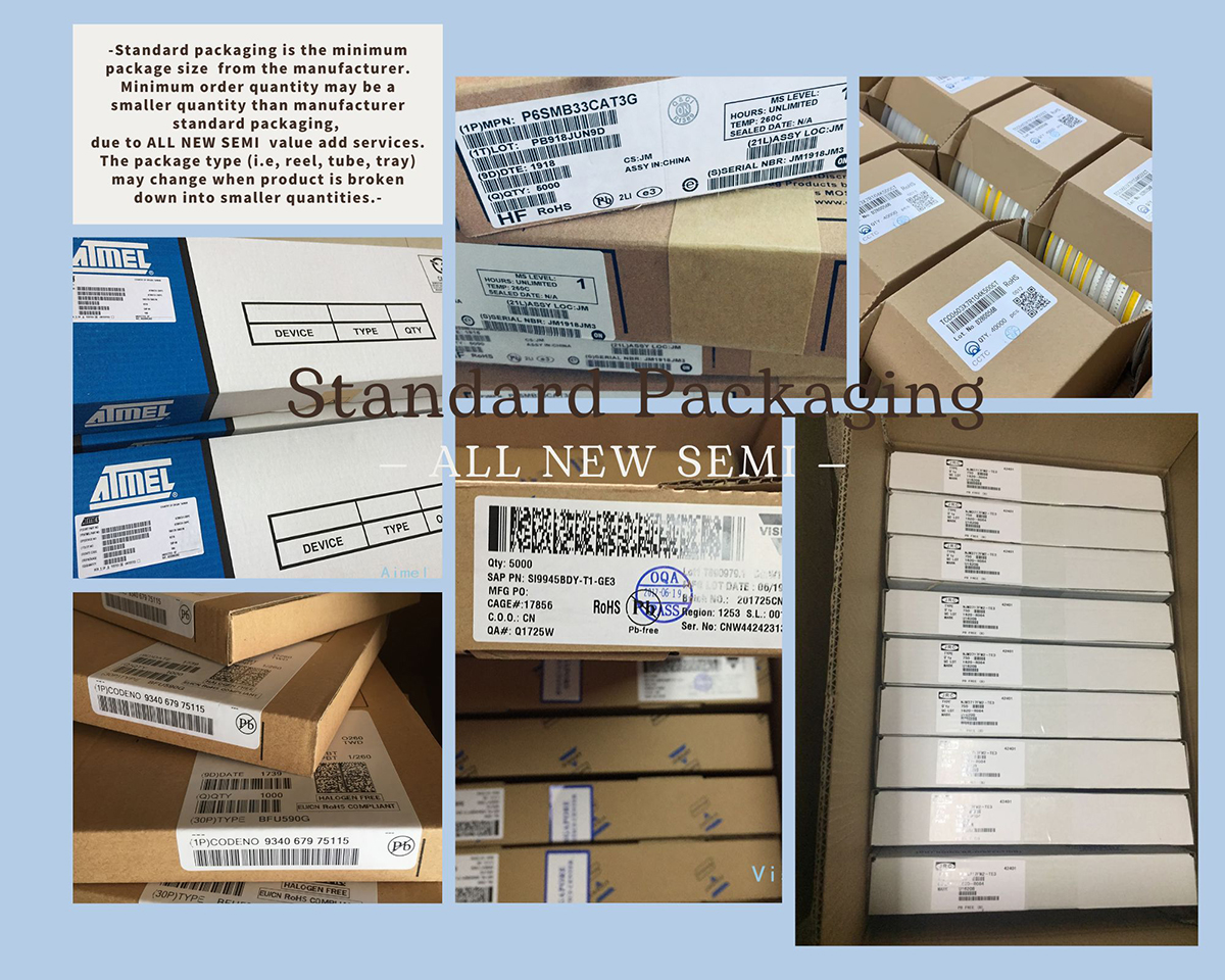
Standard packaging
We also provide :
| Part No | Manufacturer | Date Code | Quantity | Description |
| LM22676ADJ | NS | 19+ | 250 | SOP8 |
| TPS562201DDCR | TI | 22+ | 795500 | SOT23-6 |
| NJG1806K75 | JRC | 22+ | 500000 | DFN6 |
| TLV74318PDQNR | TI | 22+ | 402000 | X2SON-4 |
| NJG1801K75 | JRC | 22+ | 300000 | SMD |
| NJG1804K64 | JRC | 22+ | 300000 | DFN8 |
| LM27761DSGR | TI | 22+ | 151000 | WSON8 |
| TLV62565DBVR | TI | 22+ | 138000 | SOT23-5 |
| TPS613222ADBVR | TI | 22+ | 108000 | SOT23-5 |
| LNK625DG-TL | POWER | 22+ | 100000 | SOP-8 |
| OPA4322AIPWR | TI | 22+ | 100000 | TSSOP14 |
| TLV75528PDRVR | TI | 22+ | 99000 | WSON-6 |
| TPS7A2025PDQNR | TI | 22+ | 78500 | X2SON-4 |
| TLV62568DBVR | TI | 22+ | 72000 | SOT23-5 |
| STM32L051K8U6TR | ST | 22+ | 60000 | QFN32 |
| SKY66421-11 | SKYWORKS | 22+ | 56500 | QFN16 |
| TPS7A1111PDRVR | TI | 22+ | 54000 | WSON6 |
| TLV62569PDDCR | TI | 22+ | 52000 | SOT23-6 |
| TLV62569DBVR | TI | 22+ | 48000 | SOT23-5 |
| TPS23753APWR | TI | 22+ | 40000 | TSSOP14 |
| NB691GG-Z | MPS | 22+ | 30000 | QFN |
| SN74AHC1G02DBVR | TI | 22+ | 27939 | SOT-23 |
| TPS63000DRCR | TI | 22+ | 23238 | VSON10 |
| TLV75533PDRVR | TI | 22+ | 21500 | WSON6 |
| NB687BGQ-Z | MPS | 22+ | 20000 | QFN |
| A3916GESTR-T-1 | ALLEGRO | 22+ | 17150 | QFN-20 |
| TPS62135RGXR | TI | 22+ | 15000 | VQFN11 |
| TLE2022AMDR | TI | 0803+ | 12500 | SOP8 |
| TPS23756PWPR | TI | 22+ | 12000 | HTSSOP-20 |