

Product Descriptions
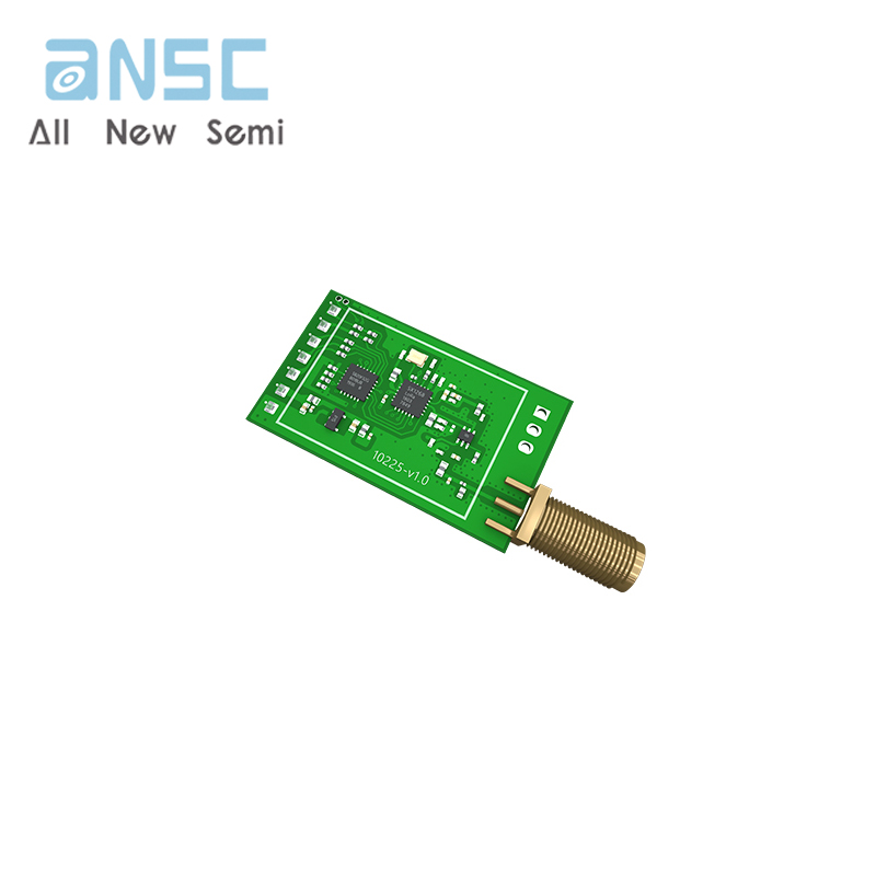
Rd-04 is a motion sensing module designed based on the X-band radar chip XBR818, with a center frequency of 10.525GHZ. The module design adopts fixed frequency, directional transmission and reception antennas (1T1R), integrating functions such as intermediate frequency demodulation, signal amplification and digital processing, and has the ability to set delay and adjust sensing range. This product has the advantages of not penetrating walls, anti-interference, small size, good suppression of clutter and high-order harmonics, high stability and consistency. In the module pulse power supply mode, the power consumption is at the microampere level. This module is mainly aimed at low-cost and low-power application fields.
Rd-04 is suitable for embedded concealed installation and is not affected by temperature/humidity, oil fume, water mist, etc. It can be widely used in various types of lamps, such as bulb lights, tube lights, ceiling lights, etc; Low power application scenarios, such as video doorbells, cat eyes, door locks, low-power cameras, smart litter boxes, feeders, etc.
Product Specifications
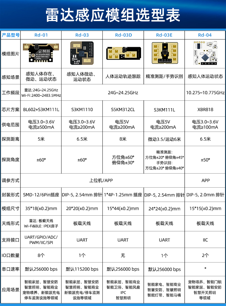
| 模组型号 Module model | Rd-04 |
| 模组封装 Module packaging | DIP-6 |
| 尺寸(mm) Size(mm) | 15.0*15.0(±0.2)MM |
| 天线形式 Antenna form | 板载天线 Onboard antenna |
| 频谱范围 Spectrum range | 10.275-10.775GHz |
| 工作环境 Work environment | -40℃~85 ℃ |
| 存储环境 Storage environment | -40℃~125°C,<90%RH |
| 供电范围 Power supply range | 供电电压3.0V~3.6V,供电电流≥100mA Supply voltage 3.0V~3.6V,supply current≥100mA |
| 支持接口 Support interfaces | IIC |
| IO口数量 Number of IO ports | 2 |
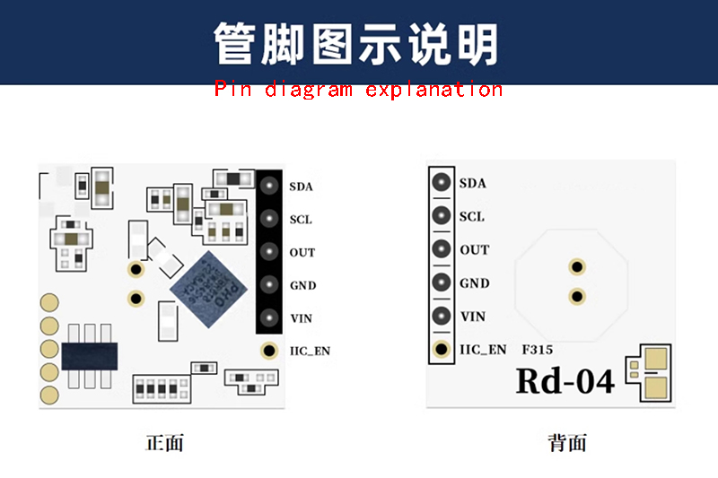
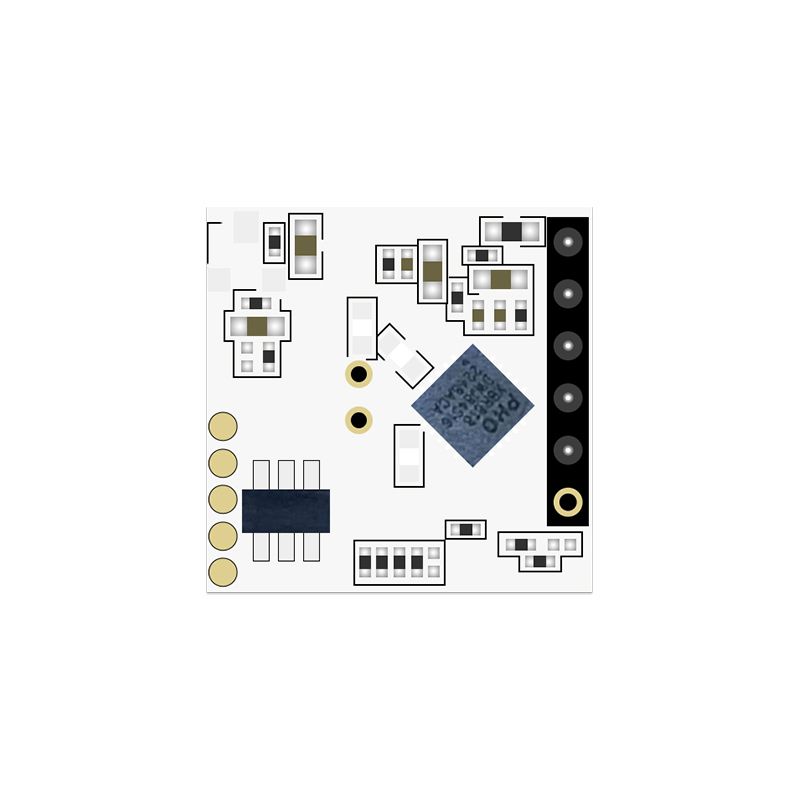
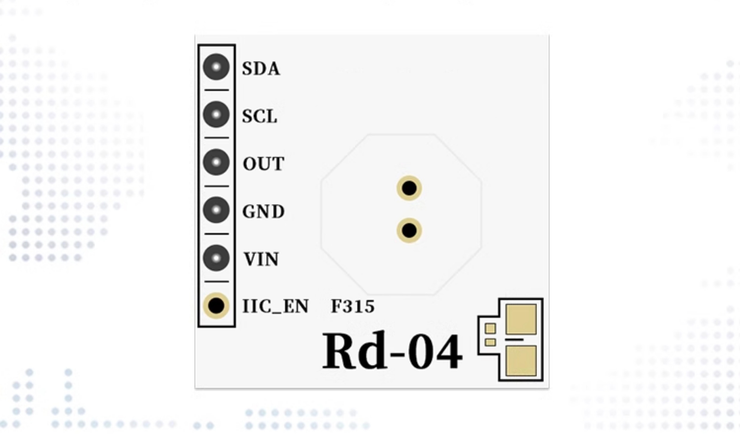
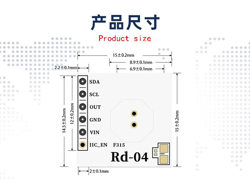
The Rd-04 module has a total of 6 pins connected, as shown in the pin diagram. The pin function definition table is the interface definition
| 脚序 Foot sequence | 名称 Name | 功能说明 Function Description |
| 1 | SDA | IIC 数据线 IIC data cable |
| 2 | SCL | IIC 时钟线 IIC clock line |
| 3 | OUT | 检测结果输出,感应时输出高电平,未感应时输出低电平 Detection result output, high level output when sensed, low level output when not sensed |
| 4 | GND | 接地 Grounding |
| 5 | VIN | 3.3V 输入电源 3.3V input power supply |
| 6 | IIC_EN | IIC 使能,当使用外部 MCU 配置 Rd-04 模式时,此 pin 脚要接外部MCU 的 IO 口,用于实现低功耗 IIC enable, when configuring Rd-04 mode with an external MCU, this pin needs to be connected to the IO port of the external MCU to achieve low power consumption |
Product Testing and usage precautions
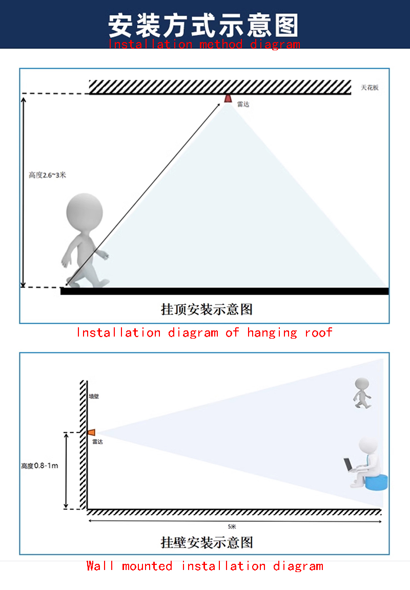
The installation position of the radar module on the motherboard is recommended in the following ways:
1. Try to ensure that the radar antenna is directly facing the area to be detected, and that there is no obstruction around the antenna;
2. To ensure that the installation position of the radar is firm and stable, the shaking of the radar itself will affect the detection effect;
3. In the presence of walls or obstacles reflecting microwaves, there will be gains in perceived distance and angle;
4. In open surroundings, there will be a decrease in perceived distance and angle; Due to the fact that even small changes can alter the detection of microwave antennas, please protect the antenna and ensure that there are no metal objects (such as solder wires) on the surface to avoid affecting the sensing distance;
5. The radar module maintains independent usage space, with a free space interval of at least 2mm around the perimeter
6. After power on, there is approximately 15 seconds for initializing noise analysis, during which it is considered abnormal sensing work;
7. During production line testing and aging operations, if a large number of radar modules are stacked together when powered on, self excitation may occur. Please ensure that a safe distance of at least 50cm is maintained between the powered radar modules,
8. In order to meet the performance of the onboard antenna, it is prohibited to place metal parts around the antenna and keep them away from high-frequency devices
The installation precautions for devices with built-in radar modules are as follows:
1. Devices equipped with radar modules should be installed away from areas with strong vibrations such as ventilation ducts, fire pipes, drainage pipes, mechanical vibrations, or large metal equipment;
2. Live working is strictly prohibited to avoid operational errors, misconnections, circuit damage, or electric shock,
3. Avoid installation in places exposed to sunlight and rain to prevent damage and affect service life;
4. The device must be installed in a place far away from electromagnetic fields to avoid electromagnetic interference and misoperation; It should also be installed in a place far away from fixed rotating or swinging objects (such as electric fans, swaying leaves, drying clothes in the wind, etc.) to avoid misoperation;
5. When installing several components with built-in radar modules, it should be ensured that the distance between each component is ≥ 0.5m
6. The antenna surface of the radar microwave module is recommended to be 3-5mm away from the product casing, otherwise it will affect the sensing distance;
7. After the device is equipped with a built-in radar module, it is recommended to place it horizontally or vertically. Within the effective sensing range, try to avoid installing two or more devices with built-in radar modules face-to-face;
8. If a device with a built-in radar module (such as a light fixture) keeps working (constantly on) and cannot be turned on or off based on moving target detection, it may be due to intermediate frequency interference on the radar module, causing the module to continuously determine that there is a moving target moving within its sensing range. At this point, the power should be turned off to check if the power supply status of the power board is normal and if the module's spatial distance has changed;
9. If the above problems cannot be solved, please turn off the power and observe the surroundings of the installation location to eliminate the influence of environmental interference factors; If the problem persists after restarting the power supply, consider replacing the device's driver power board or radar module.
This product needs to be installed in a suitable environment, and the following environments will affect the detection effect:
1. There are non-human objects that are constantly moving within the sensing area, such as animals, curtains that are constantly swinging, and large green plants facing the air outlet.
2. There are large areas of strong reflectors in the sensing area, which can cause interference when facing the radar antenna.
3. When installing on a wall, external interference factors such as air conditioning and electric fans at the top of the room need to be considered.
Product Show
Payment&Transportation

Official Certificate&Certificate
Multiple product supply

Company office environment

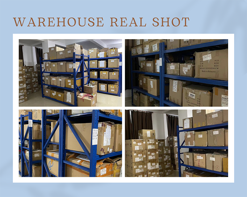
Warehouse Real Shot
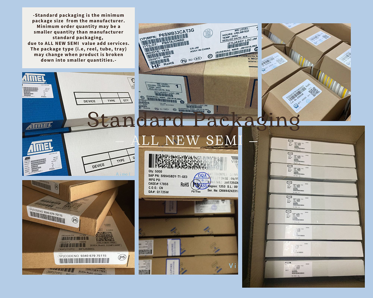
Standard packaging
We also provide :
| Part No | Manufacturer | Date Code | Quantity | Description |
| LM22676ADJ | NS | 19+ | 250 | SOP8 |
| TPS562201DDCR | TI | 22+ | 795500 | SOT23-6 |
| NJG1806K75 | JRC | 22+ | 500000 | DFN6 |
| TLV74318PDQNR | TI | 22+ | 402000 | X2SON-4 |
| NJG1801K75 | JRC | 22+ | 300000 | SMD |
| NJG1804K64 | JRC | 22+ | 300000 | DFN8 |
| LM27761DSGR | TI | 22+ | 151000 | WSON8 |
| TLV62565DBVR | TI | 22+ | 138000 | SOT23-5 |
| TPS613222ADBVR | TI | 22+ | 108000 | SOT23-5 |
| LNK625DG-TL | POWER | 22+ | 100000 | SOP-8 |
| OPA4322AIPWR | TI | 22+ | 100000 | TSSOP14 |
| TLV75528PDRVR | TI | 22+ | 99000 | WSON-6 |
| TPS7A2025PDQNR | TI | 22+ | 78500 | X2SON-4 |
| TLV62568DBVR | TI | 22+ | 72000 | SOT23-5 |
| STM32L051K8U6TR | ST | 22+ | 60000 | QFN32 |
| SKY66421-11 | SKYWORKS | 22+ | 56500 | QFN16 |
| TPS7A1111PDRVR | TI | 22+ | 54000 | WSON6 |
| TLV62569PDDCR | TI | 22+ | 52000 | SOT23-6 |
| TLV62569DBVR | TI | 22+ | 48000 | SOT23-5 |
| TPS23753APWR | TI | 22+ | 40000 | TSSOP14 |
| NB691GG-Z | MPS | 22+ | 30000 | QFN |
| SN74AHC1G02DBVR | TI | 22+ | 27939 | SOT-23 |
| TPS63000DRCR | TI | 22+ | 23238 | VSON10 |
| TLV75533PDRVR | TI | 22+ | 21500 | WSON6 |
| NB687BGQ-Z | MPS | 22+ | 20000 | QFN |
| A3916GESTR-T-1 | ALLEGRO | 22+ | 17150 | QFN-20 |
| TPS62135RGXR | TI | 22+ | 15000 | VQFN11 |
| TLE2022AMDR | TI | 0803+ | 12500 | SOP8 |
| TPS23756PWPR | TI | 22+ | 12000 | HTSSOP-20 |